Writeup
To be frank, for this challenge, i had like A LOT OF ADVICE from many of my buddies in terms of how to approach this challenge as this HUGE CREDIT TO MAH BUDDY THAT I MANAGED TO PULL INTO THIS HELLHOLE cExplr for this TISC challenge (I seriously wouldn’t have be able to do this without him man, and I learnt the MOST out of it). Solving the challenge involves 3 parts:
- Reverse Engineering of the flash dump
- Reverse Engineering of I2C communication with the implant
- Putting the puzzle together and getting the goddamn flag
RE of Flash Dump
Challenge starts off by providing a dump file of the i2c implant (command syntax used for dumping the image was via esptool, which meant that the dump we’re dealing with had something to do with ESP32). I tried out many ESP32 tools on GitHub, but the one that had the most success of carving out the various partitions is this tool:
https://github.com/BlackVS/esp32knife
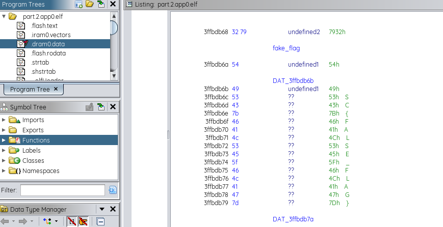
An interesting output was an ELF file, which was loaded onto mah fav disassembler Ghidra, and that’s when I knew, idk wtf I was doing. It took me a while to find out what I was reading using the various strings from the dram0.data segment (there was a fake flag and some other strings):
But apart from that, meh, kinda hit a rock wall via this approach. Let’s try interacting with the network service I2C comms.
RE of I2C Communications
An attempt was made to connect to chals.tisc24.ctf.sg via 61622 and saw a very nice ASCII diagram that indicates I2C.
- there are 3 commands: SEND, RECV, EXIT.
- after painstakingly reading so about i2c comms, there are two things that we need to find out: what addressing scheme is it using, and what is the slave address of the i2c implant.
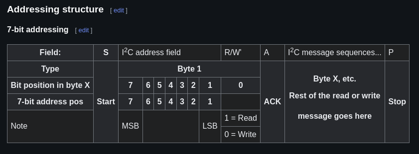
- thanks to the example written for the SEND command, we can establish that it is using a 7-bit addressing scheme (MSB contains 7-bit address value + 1-bit to determine write (0) or read (1) operation)
 After numerous automated trial and errors on the data, an amazing breakthrough appeared when the following sequence of data was sent:
SEND D2 46
SEND D3
RECV 20
Surprisingly, the returned bytes were NOT ZEROES. And it did make sense on the order of the commands given. Here’s a quick breakdown of what happened:
- For the first command, payload 46 was written to address 0x69 (SEND D2 46) on the I2C bus
- A read condition was also sent to the I2C bus so that we can read off the bytes from the same I2C bus via our buffer
- The RECV command reads the bytes off the buffer (which in this case prints out some weird bytes that are finally NOT ZERO)
And it turns out that we’ve accidentally found the slave address too, hurray for that! Now we gotta try to make sense of what we have between the disassembled code and the behavior we observed.
Back to the app
- Now that we know how to talk to the app, it’s time to figure out what caused the output.
- After going through the disassembled ESP32 code, a particular function of interest was discovered @ FUN_400d1614 that was spitting output.
- realised that using the 3 commands above, sending the payload 4D results in the CrapTPM banner to be displayed, whereas payload 46 results in an “encrypted” form of the flag.
- the encryption involves a byte-level XOR encryption as seen in the disassembled code, or what seems to be some form of a custom rolling XOR encryption (as seen in the function):
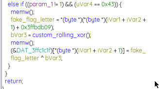
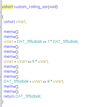
The “custom_rolling_xor” function utilises a global ‘key’ variable that aids in the XOR encryption process. What makes it even more interesting is that even though the key is an unsigned short variable (16-bit, 2 bytes), only the lower 8 bits of the key was used as the resulting value was a byte worth (8-bit).
As it is common knowledge for this CTF that the first 5 characters of the flag start with ‘TISC{’, we could do a sample XOR operation with the encrypted value for each character, however due to the bit shifts on an unsigned short variable during the key generation, reversing it back will not be possible due to possible data loss.
So this was the approach taken to obtain the flag:
-
The first XOR operation was performed between the 1st byte of the encrypted value (from the I2C bus) and the letter “T”. This is to obtain the first half (first 8-bits) of the global xor key (which is originally 16-bits).
In context, the design of the global XOR key is as follows:
|-first_half-|-second_half-|
- A brute force attack is performed to guess the second half (second 8-bits) of the global xor key. To verify if the value is correct, we have do another XOR operation with letter “I” and the 2nd byte of the encrypted value (from the I2C bus)
- Once the second half is guessed, the second half gets moved to the first half of the global XOR key, leaving the second half again for guessing.
- Steps 2 and 3 are then repeated again with the following pairs:
- “S” and 3rd byte of ciphertext
- “C” and 4th byte of ciphertext
- ”{” and 5th byte of ciphertext.
For subsequent bytes (after the ”{”), we noticed that bruteforce attacks of the second half of the global XOR key is based on the FIRST instance of the bruteforce result to generate the subsequent ciphertext values.
So with this pattern guessing method in mind, the key was then discovered for each byte. From there, just simply decrypt the ciphertext from the I2C bus with the actual key and you get the flag:
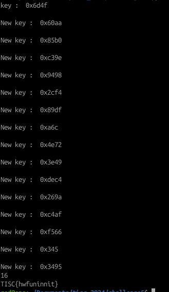
Script used is as follows below (note that this script uses recursive functions to obtain the key):
# key is global and will be reused

#!/usr/bin/python3

def custom_rolling():
    global key
    temp = (key << 7 ^ key) & 0xffff
    temp =(temp >> 9 ^ temp) & 0xffff
    key = (temp << 8 ^ temp) & 0xffff

    return key

# for i in range(0xff):
#     check = []
#     key = 0x4f
#     key = (i<<8)|key
#     temp_key = key

#     custom_rolling()
#     if (key&0xff) == 0xaa:
#         print("key : ", hex(temp_key))
#         print("FOUND")

#after 1 round of rolling
key = 0x6d4f

possible_key = [0x6d4f]
print("key : ", hex(key))

custom_rolling()
print("\nNew key : ", hex(key))
possible_key.append(key)

custom_rolling()
print("\nNew key : ", hex(key))
possible_key.append(key)

custom_rolling()
print("\nNew key : ", hex(key))
possible_key.append(key)

custom_rolling()
print("\nNew key : ", hex(key))
possible_key.append(key)

custom_rolling()
print("\nNew key : ", hex(key))
possible_key.append(key)

custom_rolling()
print("\nNew key : ", hex(key))
possible_key.append(key)

custom_rolling()
print("\nNew key : ", hex(key))
possible_key.append(key)

custom_rolling()
print("\nNew key : ", hex(key))
possible_key.append(key)

custom_rolling()
print("\nNew key : ", hex(key))
possible_key.append(key)

custom_rolling()
print("\nNew key : ", hex(key))
possible_key.append(key)

custom_rolling()
print("\nNew key : ", hex(key))
possible_key.append(key)

custom_rolling()
print("\nNew key : ", hex(key))
possible_key.append(key)

custom_rolling()
print("\nNew key : ", hex(key))
possible_key.append(key)

custom_rolling()
print("\nNew key : ", hex(key))
possible_key.append(key)

custom_rolling()
print("\nNew key : ", hex(key))
possible_key.append(key)

print(len(possible_key))

TPM_val = [0x1b,0xe3, 0xe3, 0xdd, 0xe3, 0x9c, 0xa8, 0x0a, 0x07, 0x27, 0xad, 0xf4, 0xc1, 0x0f, 0x31, 0xe8]

flag = ""
for i in range(len(possible_key)):
    flag += chr(TPM_val[i] ^ (possible_key[i] & 0xff))

print(flag)
Flag: TISC{hwfuninnit}
Thoughts
Not going to lie but i was initially lost in this, but it took me a considerable amount of time to understand not only the Ghidra output but also the bit shifts (both left and right) that really threw me off many times. But thankfully with some guidance, i was able to do it, and i totally learnt alot from this!